Important:Analysis of influencing factors on diode
Analysis of influencing factors on diode junction temperature testing
Abstract:
The bypass diode is an important component of photovoltaic modules, mainly to prevent thermal spot effect and avoid power generation loss. The junction temperature of a diode at a certain current is an important parameter for evaluating the quality of the diode, which affects the quality of photovoltaic modules. This article explores the influence of several factors such as wind speed, voltage acquisition, and diode position on the junction temperature of diodes.
1. Preface
The bypass diode is an important component of photovoltaic modules, mainly to prevent thermal spot effect and avoid power generation loss. The junction temperature of a diode at a certain current is an important parameter for evaluating the quality of the diode, which affects the quality of photovoltaic modules. Childs et al. proposed several methods for testing junction temperature [1-5], and the IEC61215 standard provides a method for pulse current. This paper explores the influence of factors such as wind speed, voltage acquisition accuracy, and diode position on the results of junction temperature testing according to the testing method of IEC61215.
2. Test Introduction
The test schematic is shown in Figure 1.
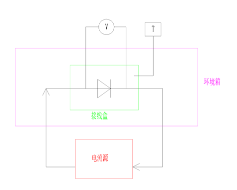
Figure 1. Schematic diagram of diode testing
Remarks:
环境箱-Environmental box,接线盒-Junction box,电流源-Current source
The diode is installed inside the junction box, and the temperature of the junction box is controlled by the environmental box. Pulse current and constant current can be passed into the diode. The voltage across the diode and the surface temperature of the junction box can be monitored. For specific testing steps, please refer to the IEC61215 MQT19 standard.
In order to study the influencing factors of diode junction temperature testing, we designed schemes such as changing the voltage acquisition line, changing the relative position between the junction box and the sample, and changing the position of the sample in the environmental box to test the junction temperature of diodes in the same junction box.
3. Results and Discussion
3.1 The influence of voltage acquisition wire diameter on test results
We used 5 different voltage acquisition wire diameters with cross-sectional areas of 0.2mm ², 0.5mm ², 1mm ², 2.5mm ², and 4mm ², respectively. The corresponding test results are shown in Table 1 and Figure 2.
Table 1. Relationship between voltage acquisition line diameter and junction temperature
Cross-sectional area(mm²) | Junction temperature(℃) |
0.2 | 185 |
0.5 | 182 |
1 | 170 |
2.5 | 150 |
4 | 110 |
Figure 2. Relationship between voltage acquisition line diameter and junction temperature
From Table 1 and Figure 2, it can be seen that the junction temperature decreases rapidly with the increase of the voltage acquisition line diameter. This is because the acquisition line is connected to the lead of the diode, and the heat of the diode is dissipated through the voltage acquisition line. The larger the wire diameter, the faster the heat dissipation, and the tested diode junction temperature is lower.
3.2. The influence of the position of the junction box in the sample on the junction temperature
We set the junction box at 9 points on the sample, and its distribution is shown in Figure 3.
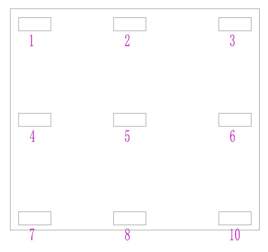
Figure 3. Distribution of junction boxes on the sample
The junction temperature data obtained from the test are shown in Table 2.
Table 2: Data Table of Junction Temperature and Location
Point | 1 | 2 | 3 |
Junction temperature (℃) | 181.5 | 184.2 | 182.1 |
Point | 4 | 5 | 6 |
Junction temperature (℃) | 183.2 | 192 | 182.5 |
Point | 7 | 8 | 9 |
Junction temperature (℃) | 180.4 | 185.1 | 181.3 |
The distribution map is shown in Figure 4:
Figure 4 Relationship between junction temperature and position
From Figure 4, it can be seen that the closer to the middle position of the sample, the higher the junction temperature data.
This is related to the heat dissipation conditions on the surface of the junction box, as shown in Figure 5. The wind speed of the environmental box is a structure with upper air outlet and lower air return. The closer it is to the middle of the sample, the lower the wind speed on the surface of the junction box, the worse the heat dissipation conditions, and the higher the junction temperature.
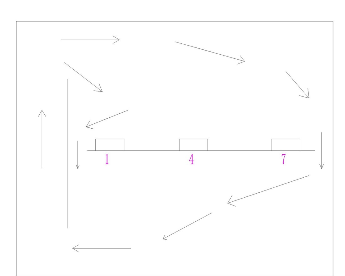
Figure 5. Schematic diagram of wind direction inside the environmental box
3.3 Relationship between the position of the sample in the environmental chamber and the junction temperature
We placed the samples in the upper, middle, and lower positions of the environmental chamber, as shown in Figures 6, 7, and 8.
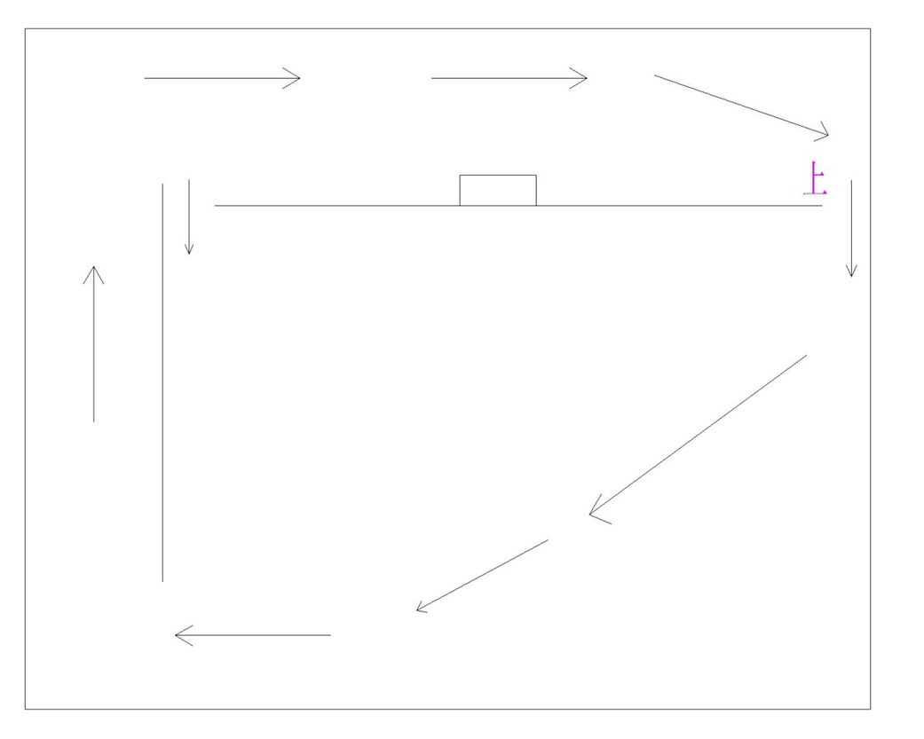
Figure 6. Schematic diagram of placing the sample on the upper part of the environmental chamber
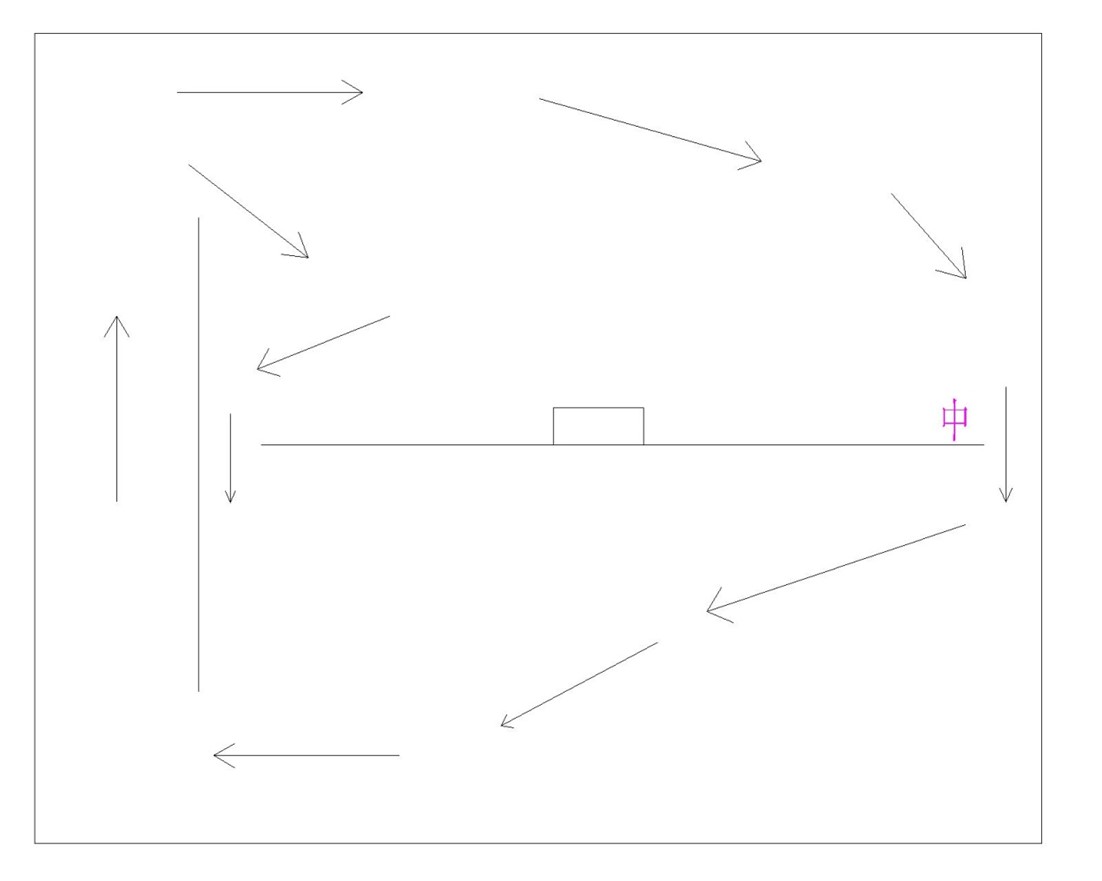
Figure 7. Schematic diagram of placing the sample in the middle of the environmental chamber
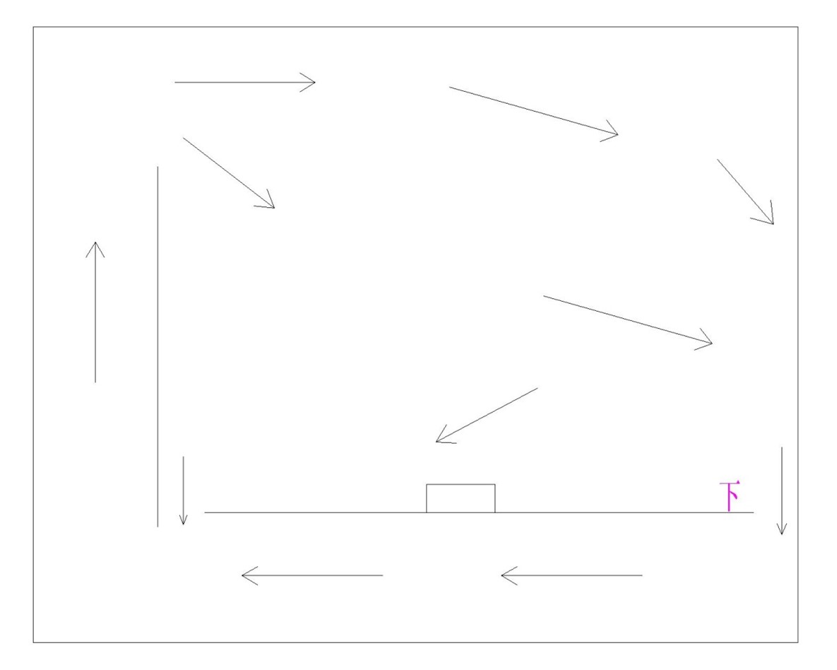
Figure 8. Schematic diagram of placing the sample at the bottom of the environmental chamber
The results of its junction temperature test are shown in Table 3.
Table 3. Table of environmental chamber location and junction temperature
Position | Upper | Middle | Lower |
Junction temperature (℃) | 184 | 192 | 187 |
The relationship diagram is shown in Figure 9:
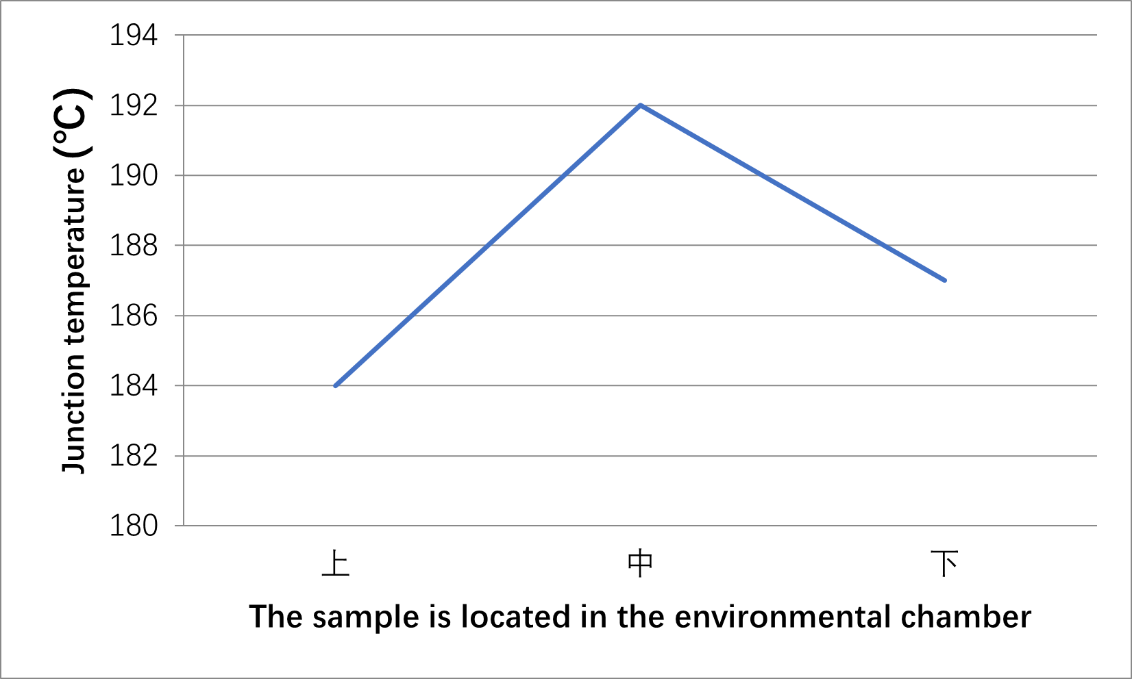
Remarks: 上-Upper,中-Middle,下-Lower
Figure 9. Relationship between junction temperature and sample position
From Table 3 and Figure 9, it can be seen that the junction temperature of the sample placed in the middle of the environmental chamber is the highest, followed by the junction temperature of the sample placed in the lower part, and the junction temperature of the sample placed in the upper part is the lowest. From Figures 6, 7, and 8, it can be seen that this is related to the wind speed on the surface of the junction box. With high wind speed and good heat dissipation conditions, the tested junction temperature is low. The wind speed is low, the heat dissipation conditions are poor, and the tested junction temperature is high.
4. Conclusion
There are many factors that affect the diode junction temperature test, including sample preparation, the relative position between the junction box and the sample, and the placement of the sample in the environmental chamber. When the heat dissipation conditions during the diode testing process are good, the tested junction temperature is low, and the heat dissipation conditions are poor, the tested junction temperature is high.
Reference
[1]Childs, P.R.N.; Greenwood, J.R.; Long, C.A. Review of Temperature Measurement. Rev. Sci. Instrum. 2000, 71, 2959–2978. [Google Scholar] [CrossRef]
[2]Blackburn, D.L. Temperature Measurements of Semiconductor Devices—A Review. In Proceedings of the Twentieth Annual IEEE Semiconductor Thermal Measurement and Management Symposium (IEEE Cat. No.04CH37545), San Jose, CA, USA, 11 March 2004; pp. 70–80. [Google Scholar]
[3]Avenas, Y.; Dupont, L.; Khatir, Z. Temperature Measurement of Power Semiconductor Devices by Thermo-Sensitive Electrical Parameters—A Review. IEEE Trans. Power Electron. 2012, 27, 3081–3092. [Google Scholar] [CrossRef]
[4]Baker, N.; Liserre, M.; Dupont, L.; Avenas, Y. Improved Reliability of Power Modules: A Review of Online Junction Temperature Measurement Methods. IEEE Ind. Electron. Mag. 2014, 8, 17–27. [Google Scholar] [CrossRef] [Green Version]
[5]Kalker, S.; Ruppert, L.A.; Van der Broeck, C.H.; Kuprat, J.; Andresen, M.; Polom, T.A.; Liserre, M.; De Doncker, R.W. Reviewing Thermal Monitoring Techniques for Smart Power Modules. IEEE J. Emerg. Sel. Top. Power Electron. 2021, 10, 1326–1341. [Google Scholar]


